Overview & Layout
 |
This page provides an overview to the different components in the system and information on siting and aligning those different components. Also shown here are the two different layout versions that have been used. v1.0 was located on a wooden workbench in a below grade basement laboratory. v2.0 consists of a small thermally controlled enclosure located some distance from any house or other structure.
|
System Components
The magnetometer setup consists of several major components:
- Laser
- Laser diode and associated circuit board removed from a consumer-grade laser pointer and mounted in a two-axis positioning mount. The mount is made of wooden scraps, has a three-point screw leveler, and features a three-point angle positioner made from three 10-32 machine screws, wing nuts, and springs. This mount will be recognizable to those who familiar with telescope mirror mounts. The height of the laser diode is approximately equal to the mirrors on the balance; the leveling screws provide a fine height adjustment if necessary. The convenience of this sort of mounting cannot be overstated. It is steady, easy to adjust, and reliable. It also cost about US$2.00 in parts and took about one hour to build. Just do it.
- Nulling Magnet Assembly
- This was built as described in the Amateur Scientist article and includes the three-point screw leveler.
- Detector
- The detector is fully described on another page. It is mounted on a tall vertical arm which is, in turn, affixed to a flat wooden plate with a three-point screw leveler. The actual detector is attached to the arm with a wooden clothespin glued to the rear of the detector enclosure. This attachment allows for easy vertical and horizontal alignment.
- Balance & Drive Coils
- The balance was also built as described in the article and is mounted to a wooden plate with, you guessed it, a three-point screw leveler. In this case, the leveler is especially helpful as the vertical axis of the balance is decidedly non-vertical. The leveler fixes this in a jiffy. The base is large enough to allow mounting of the Helmholtz Pair of Drive Coils; the details of which are provided on another page. Note that the cylindrical axis of the coils matches the poles of the sensing magnets when those magnets are at rest.
- Electronics Package
- The v1.0 electronics package was built upon a prototyping breadboard with triple DC supplies. The breadboard consists of an array of partially interconnected holes with internal spring contacts. Component leads and jumper wires are pushed into the holes to make up the circuit. The power supplies deliver +5, +15, and -15 volts. The +5V supplies power to the laser diode which consumes only 30 mA of current. The ±15V supplies power the op-amp circuitry and the coils themselves.
- The second and current electronics package is also built on a prototyping breadboard but is powered by a pair of power supplies which deliver +15 and -15 volts. IC regulators are used to provide lower voltages.
Magnetometer v1.0 System Configuration
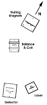 |
The orientation of these major components can be seen in the figure to the left. Especially important is the orientation with regard to the local terrestrial North-South direction. Actually, I find that the balance, laser, and detector can be oriented in just about any direction but the nulling magnet assembly is often best located on the North-South line relative to the balance. The nulling magnet assembly can be translated along this line and can be rotated to provide suitable alignment. Alignment is achieved when the bright red spot of the laser diode falls upon the center of the detector and the lengthening of the period of oscillation occurs as described in the article. However, the nulling magnet assembly does not have to be located to the North of the balance; it can be located to the South but it will have to be rotated by 180° for proper operation.
It is worth repeating that the nulling magnet assembly must be located on the North-South line relative to the balance. If you find that the assembly's optimum position lies elsewhere then it is likely that there is a significant perturbation in the earth's magnetic field due to some local ferrous material. Moving the system to another location is advisable under these circumstances as there is likely to be considerable interference with the real terrestrial signal.
Most of the dimensions are not critical. The laser rests about 60 cm from the balance as does the detector. The angular sensitivity of the detector is directly related to its distance from the balance. If you project the spot on a distant (several meters) wall it is remarkable how much it will "dance around". However, this is a case where more isn't necessarily better.
The mounting surface is worth noting. All of the components are mounted on a wooden workbench which in turn rests on a concrete foundation in the basement of my house. Overall, mechanical or seismic issues are not affecting the system nor are they the biggest problem.
|
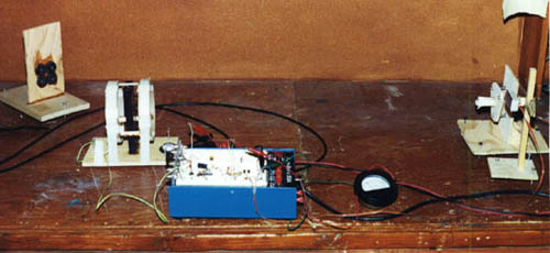
Here's a front view of the components on the workbench:
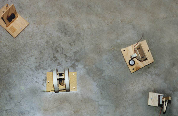
Here's an overhead image of the components laid out on a concrete floor just for display:
Magnetometer v2.0 System Configuration & Layout
After several months operation the v1.0 setup was disassembled and moved to an outdoor location inside of a thermally controlled enclosure. Thermal control is important as the magnetic field strength of a permanent magnet displays significant temperature dependence. The enclosure is described more fully on another page but the orientation of the system components is described on this page.
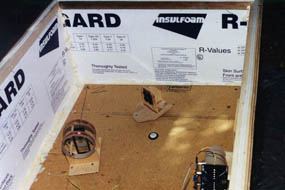
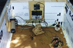
In the image to the above left, the interior of the enclosure can be seen facing approximately north. a true north-south line can be seen drawn on the floor. The balance is oriented on the north-south line with the balancing magnets off to the east. This orientation was found to yield good results.
In the above right image, the view is approximately to the south. The laser and detector can be seen in this image; they are located on equidistant from the north-south line on opposite sides of it. In this configuration, the resting position of the torsion balance magnet is along the north-south line.
The electronics package can also be easily seen in the south facing image. The entire package is mounted to the inside of the south wall and consists of a dual ±15 volt power supply, the acquisition microcomputer, the prototype breadboard containing the control loop circuitry, and a 115VAC power distribution strip, respectively from top to bottom. At the far, left the exhaust end of the temperature controller assembly can be seen. At the far right of the north facing image, the intake end of the same temperature controller assembly can be seen. More on this assembly on another page.
Home |
Graph Data |
Text Data |
Layout |
Detector |
Laser |
Coil |
Electronics |
Enclosure |
Acquisition
Linearity Analysis |
Harmonic Analysis |
References |
Operator Log

 Copyright © 2001, 2002, 2003 XTR Systems, LLC
All Rights Reserved
Send comments to: Webmaster


