This page details the mounting used to hold and position the laser diode plus some other information pertaining to the laser.
| Home | Graph Data | Text Data | Layout | Detector | Laser | Coil | Electronics | Enclosure | Acquisition | Linearity Analysis | Harmonic Analysis | References | Operator Log |
 |
This page details the mounting used to hold and position the laser diode plus some other information pertaining to the laser. |
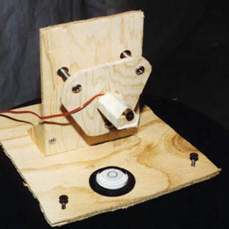
 The front of the mount is shown at the left. a laser pointer was disassembled and the laser diode was removed together with its associated circuit board. a pair of fine, flexible wires was carefully soldered to the circuit board which connect to a 5V DC power supply. In Version 2, 5 volts is supplied to the laser by connection to the -15 volt supply through a fixed voltage dropping resistor.
The diode is attached to the horizontal wooden arm of the mount with masking tape. In turn, the arm is attached to a floating wooden plate supported by three spring-loaded adjustment screws. The screws allow for smooth, stable, and fine adjustment of the pointing direction of the laser. The horizontal mounting plate is supported on three long medium pitch screws useful for leveling the mount and for fine adjustment of the laser elevation (which should be approximately the same for the laser, balance mirror, and detector).
A circular spirit level can be seen on the horizontal mounting plate. It is not permanently attached and it moved around to level each of the system components.
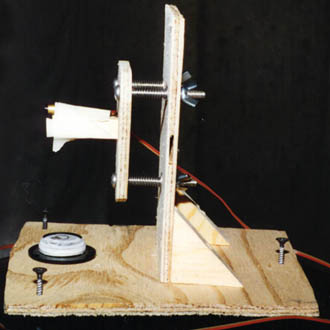
 The side view at the right shows the wing nuts and location of the springs. Other mounting arrangements can undoubtedly be devised which provide for two orthogonal adjustments but I did not spend much time pondering them. In practice, I adjust the two top screws until the laser spot is shining on the balance's damping penny directly above the suspended mirror. Then, I adjust the bottom screw until the spot is directly on the mirror. a final tweak of all three nuts to yield the brightest spot of reflected light falling on the detector's ground glass face is all that is necessary to complete the operation.
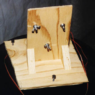
 The rear of the mount is shown here just in case you have a hard time visualizing any of the locations of components. The dimensions of the mount are not critical and it is obvious that my wood working technique is not all that great.
It is also worth noting that the lifetime of the laser seems (like everything else) to be finite. I have already had one unit fail on me after approximately one month of continuous use. When it failed the current draw increased several fold and the light output decreased significantly. a replacement unit was obtained and installed in the system. I will report on its failure if and when it occurs.
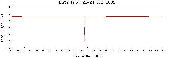
Since the Version 2 magnetometer is relatively inaccessible, monitoring the laser output remotely has become more important. This has been accomplished by taking the two photodetector signals, adding them together, and logging that sum value. Manual experiments showed that the sum is not constant as the laser spot sweeps across the detector face however it is significantly higher than when the laser is absent from the detector face. Additionally, in normal operation, the control loop keeps the laser spot centered on the detector so under locked conditions the sum signal can be used as a relative figure of merit indicating the status of the laser. A sample graph showing this laser output is shown below:

Home |
Graph Data |
Text Data |
Layout |
Detector |
Laser |
Coil |
Electronics |
Enclosure |
Acquisition
Linearity Analysis |
Harmonic Analysis |
References |
Operator Log
![]()
 Copyright © 2001, 2002, 2003 XTR Systems, LLC
All Rights Reserved
Send comments to: Webmaster