Environmental Enclosure
During the August-September 2000 refurbishment, the magnetometer was moved from the thermally stable but magnetically dirty basement laboratory to new magnetically cleaner but thermally unstable location outside and away from any building. Of course, it could not be left outside exposed the elements so an enclosure was built to provide a controlled environment. An accessory temperature controller was included to maintain a constant temperature and digital link was created to ferry the recorded data back into the laboratory.
The enclosure can be seen in the accompanying images in various states of assembly to show the different techniques used in its construction. Many of the materials can be found around the house or at a local hardware store at a 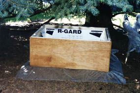 modest cost. Approximately 4'x3'x2' (LxWxH) in external dimensions, the enclosure consists of a wooden frame built with two-by-two stock covered on the four sides with 0.25" thick plywood, chip board, or particle board (whatever was available in the junk box. The top was left open to accept a 0.25" thick plywood lid; the bottom was also left open to accept a false floor. The vertical two-by-twos extended about 6" below the sides with pointed tips and were driven into the ground for anchoring.
A quiet, shaded location was found beneath a large native Colorado Blue Spruce tree which was cleared of dead branches. The ground was leveled and excavated to a depth of a few inches. 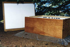 a layer of heavy vinyl plastic was placed over the excavation, small undersized cuts were made at the locations of the vertical stakes and the enclosure was driven home and roughly leveled using a heavy hammer. The soil surrounding the base was mounded up against the walls and the vinyl was left draped over the mound. The inside of the walls was filled with 1.5" thick styrofoam construction insulation and held in place with plenty of constructive adhesive.
a false floor from another piece of 0.25" particle board cut about one inch smaller than the interior of the enclosure. Three two-by-two stakes were driven through small cuts in the vinyl, leveled, and the floor space filled with styrofoam "peanuts". 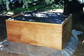 The false floor was screwed down onto the stakes and the gaps at the edges filled with self-expanding insulating foam which was trimmed back after hardening. The outside walls were sealed against moisture using many spray cans of clear acrylic sealant. Any gaps in the insulation on the walls was touched up with the self-expanding foam. The result is a draft free, physically stable, and clean chamber.
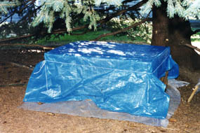 The lid was also sealed on the outside with acrylic and lined on the inside face with 1.5" thick styrofoam as with the walls. The top surface of the walls was lined with weather stripping to ensure a good seal with the lid. When the lid is fitted in place another piece of vinyl is placed over the whole enclosure and held in place with a piece of light rope. This provides for a rain shield and helps reduce any drafts due to gaps near the lid.
After the completion of the construction it was necessary decide upon an operating temperature for the interior of the enclosure and to design a device for maintaining that temperature. There are several design considerations which go into the selection of the operating temperature. It must be high enough so that regulation can be maintained during the heat of summer. It must be a low as possible to require the smallest size of heater. It must also be as low as possible to reduce the temperature induced degradation of the electronic components used in the chamber. a temperature of approximately 28°C (82.4°F) was finally chosen; high enough to make it through the late summer months at the location. It is possible that next summer the operating temperature may have to raised a bit.
Enclosure Internal Layout
The image at the left shows the North facing view inside of the enclosure, the right shows South. Several of the components rest on the floor without any fastening. These include the Balance/Drive Coil assembly, Nulling Magnet assembly, Laser, and Detector. Each of these was leveled using a spirit level using the three-point 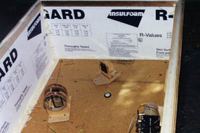 mounting upon which each rests. The Balance is situated on the North-South line (visible in the left image) and the Laser and Detector are placed to the South, equally spaced from the North-South line. The position of the Nulling Magnets was determined to be to the North-East of the Balance.
Several other major components are mounted on the walls of the enclosure; two such assemblies are used, one on the East wall and one on the South. They each consist of a 0.25" thick piece of plywood screwed into the 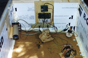 two-by-two frame with various components mounted on the plywood.
The South assembly consists, from top to bottom, of a ±15V DC power supply, the acquisition micro-computer, the prototype board containing the electronics package, and a 115VAC power distribution strip. The AC power enters the enclosure through a wall perforation which was later sealed with silicone and self-expanding foam.
The East assembly contains the Temperature Controller which is described below. The laser light can be seen as a red spot on the face of the Detector in the image at right.
Temperature Controller
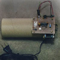
The purpose of the Temperature Controller is to measure the temperature within the enclosure and introduce heat enough to maintain that temperature within specified limits. The assembly consists of a 4" DC fan (from an old external disk drive case), a thermistor (temperature-sensitive resistor, salvaged from a discarded household thermostat), a 115VAC powered heating element, a heavy-walled cardboard tube chimney, and some control electronics. The fan pulls air past the thermistor (seen at the end of the coiled wires at the right of the figure at the left), forces it past the heating element located inside the chimney and returns it to the enclosure at large.
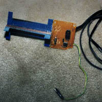
The heating element is constructed from two pieces of blue perforated circuit board cut into exaggerated "H" shapes and fitted together to make an "X" when viewed from the end. a length of nichrome resistance wire is wound along the form made by the boards and connected to 115VAC through an optically-coupled TRIAC (a solid state power switch). Using an optically-coupled switch isolates the dangerous line voltage from the rest of the circuitry. The heating element and the power control circuit are inserted in the chimney. The circuitry is on the upwind side of the heater and includes a thermal fuse which will disable the heater in the event the fan fails. The heater assembly is shown in the image at the right. The coils of heater wire can be seen in the end-on image below.
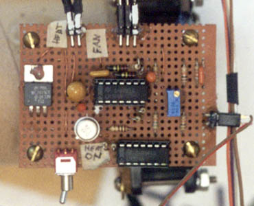
The circuitry converts the internal temperature into a voltage, compares that voltage to an adjustable voltage (which is used to establish the desired set temperature) and turns on the heater power until the difference between the voltages is minimized. The fan operates constantly and the chimney is oriented so that 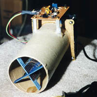 temperature gradients in the enclosure are minimized. The circuitry also supplies a conditioned copy of the measured temperature voltage to the Acquisition Microcomputer to permit remote monitoring of the internal temperature. Additionally, a similarly conditioned copy of the power demand signal, proportional to the actual thermal power being delivered by the heater is also sent to the Acquisition Microcomputer for remote monitoring.
An important design issue which cannot easily be determined theoretically is the electrical/thermal size of the heater. The specific question to be answered is how much thermal power is needed to maintain the internal temperature a given value given the expected external weather conditions. It is possible to model the problem as a first order differential process with the heat loss in Watts is proportional to the difference between the internal and external temperatures in °C. The constant of proportionality would then be the consolidated thermal resistance of the enclosure in units of W/°C. The validity of this model and the constant can be easily determined by closing up the enclosure with a manually controlled heater and temperature sensor inside and an external temperature sensor and measuring the steady-state temperature differential for a varied set of heater powers and external temperatures.
Those measurements were carried out and a thermal resistance determined to be 3.0±1.0 W/°C. There is large error range but the accuracy is adequate to provide rough guidance to the design. With an internal set temperature of +28°C and an estimated worst case external temperature of -30°C (-22°F) the 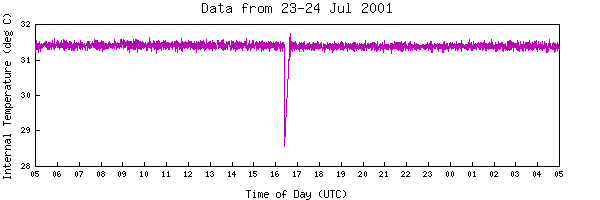 worst case temperature difference is 58°C. The power required is 174±58 W. a heater power of 240 W was selected to provide an additional margin. This heater consisted of 55 ohms of #30 AWG nichrome wire (2.5 m length) wound on the form as described above. When driven with 115VAC (RMS) a current of 2.1A (RMS) is drawn and 240 W is developed. By spacing the wire out on the form and with the airflow provided with the fan the coupling of the wire with the airflow was so efficient that the wire did not glow, a definite safety plus. Failure of the fan resulted in an immediate rise in the temperature of the wire and a medium orange glow until the relatively quick opening of the thermal fuse.
With the return of warm weather it became apparent that an internal temperature of+28°C wasn't high enough to provide sufficient headroom for the heater so it was raised to approximately +31°C where it operates currently.
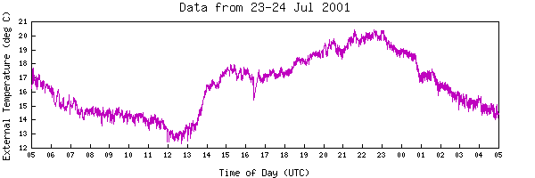
During routine operation of the magnetometer the internal enclosure temperature, the external ambient temperature, and heater power are recorded along with the actual science data. Over the course of 24 hours, the controller is able to maintain the enclosure temperature within a few tenths of one degree Celsius. This stability is due to the inclusion of an integral term in the temperature controller. Although the basement laboratory which was the site of the Magnetometer v1.0 was not instrumented with a recording thermometer, a small digital wall thermometer displayed dinural variations of as many as several degrees Celsius. The heater power can be seen to roughly track the external temperature over the course of a day. Long-term monitoring shows that the heater power is adequate to maintain the desired internal temperature without approaching 100% of its capacity. We'll see how well the higher internal temperature is maintained when the cooler seasons return and especially when the temperature dips in the night. 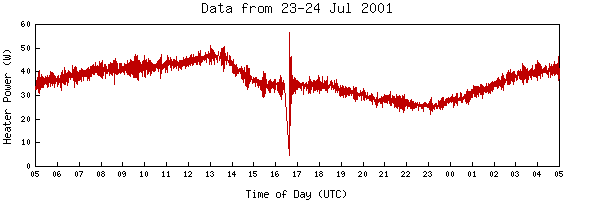

 modest cost. Approximately 4'x3'x2' (LxWxH) in external dimensions, the enclosure consists of a wooden frame built with two-by-two stock covered on the four sides with 0.25" thick plywood, chip board, or particle board (whatever was available in the junk box. The top was left open to accept a 0.25" thick plywood lid; the bottom was also left open to accept a false floor. The vertical two-by-twos extended about 6" below the sides with pointed tips and were driven into the ground for anchoring.
 a layer of heavy vinyl plastic was placed over the excavation, small undersized cuts were made at the locations of the vertical stakes and the enclosure was driven home and roughly leveled using a heavy hammer. The soil surrounding the base was mounded up against the walls and the vinyl was left draped over the mound. The inside of the walls was filled with 1.5" thick styrofoam construction insulation and held in place with plenty of constructive adhesive.
 The false floor was screwed down onto the stakes and the gaps at the edges filled with self-expanding insulating foam which was trimmed back after hardening. The outside walls were sealed against moisture using many spray cans of clear acrylic sealant. Any gaps in the insulation on the walls was touched up with the self-expanding foam. The result is a draft free, physically stable, and clean chamber.
 The lid was also sealed on the outside with acrylic and lined on the inside face with 1.5" thick styrofoam as with the walls. The top surface of the walls was lined with weather stripping to ensure a good seal with the lid. When the lid is fitted in place another piece of vinyl is placed over the whole enclosure and held in place with a piece of light rope. This provides for a rain shield and helps reduce any drafts due to gaps near the lid.
 mounting upon which each rests. The Balance is situated on the North-South line (visible in the left image) and the Laser and Detector are placed to the South, equally spaced from the North-South line. The position of the Nulling Magnets was determined to be to the North-East of the Balance.
 two-by-two frame with various components mounted on the plywood.

 temperature gradients in the enclosure are minimized. The circuitry also supplies a conditioned copy of the measured temperature voltage to the Acquisition Microcomputer to permit remote monitoring of the internal temperature. Additionally, a similarly conditioned copy of the power demand signal, proportional to the actual thermal power being delivered by the heater is also sent to the Acquisition Microcomputer for remote monitoring.
 worst case temperature difference is 58°C. The power required is 174±58 W. a heater power of 240 W was selected to provide an additional margin. This heater consisted of 55 ohms of #30 AWG nichrome wire (2.5 m length) wound on the form as described above. When driven with 115VAC (RMS) a current of 2.1A (RMS) is drawn and 240 W is developed. By spacing the wire out on the form and with the airflow provided with the fan the coupling of the wire with the airflow was so efficient that the wire did not glow, a definite safety plus. Failure of the fan resulted in an immediate rise in the temperature of the wire and a medium orange glow until the relatively quick opening of the thermal fuse.

