 |
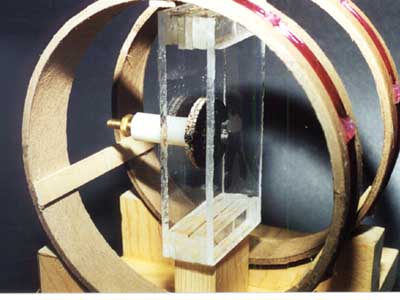
This page details the Drive Coil set which generates a small experimentally controllable magnetic field and the Torsion Balance Magnetometer (TBM) itself. During normal operation this magnetic field is automatically adjusted so as to keep the Torsion Balance in balance, i.e., at its zero or null position. Since the Balance is sensitive to the sum of all of the magnetic fields to which it is exposed and it is at its zero position, the magnetic field generated by the Drive Coil set is a direct measure of the other magnetic fields. The Drive Coil set is driven by a Voltage-Controlled Current Source as described in another section. A Torsion Balance Magnetometer consists of a strong Sensor Magnet rigidly attached to a mirror and suspended by a strong fiber which constrains its motion to a single degree of freedom, rotation about the long axis of the fiber. A highly conductive piece of non-ferrous metal immersed in the field of the Sensor conveniently provides a dampening force. |
 When an experimenter wishes to create an magnetic field using an electromagnet several questions arise immediately: What is the required field strength and what is the current available to generate it? What will the physical configuration of the coils be and what physical access to the experimental region is required? How much will the resulting field vary from point-to-point in space, i.e., how spatially homogeneous will the field be?
Basic physics texts state that an infinitely long solenoidal coil will yield the most homogeneous field at its center but this is neither physically realizable nor is it very practical. Solenoids with length to diameter a ratio of ten can create very homogeneous fields while a ratio of four work fairly well for many applications. However, in all of these cases the experimental access remains rather limited. Often, access the experimental space "from the side" is required rather than along the long axis. Solenoids simply don't permit this type of access. To address this situation an alternate physical coil configuration is often used and is called a Helmholtz Pair, after the 18th century physicist who first analyzed and described it.
A Helmholtz Pair is a pair of circular coils of the same diameter, with coincident axes, the same number of wire turns wound in the same direction, and separated by a distance equal to their radius. This configuration will yield a maximally homogeneous field at the point midway between the coils on the cylindrical axis. With a little calculus you too can derive the equations. The field isn't quite as good as a solenoid but it's quite decent and most importantly the experimental region is now much more accessible.
 The field strength at the center of a Helmholtz Pair is given by th following relation:
 ![]() Where n is the number of turns in each of the two coils (both coils must have the same number of turns), i is the current flowing through the coils in amperes, r is the radius of the coils in cm, and b is the magnetic field in gauss (actually oersteds to be strictly correct). In the current case:
Where n is the number of turns in each of the two coils (both coils must have the same number of turns), i is the current flowing through the coils in amperes, r is the radius of the coils in cm, and b is the magnetic field in gauss (actually oersteds to be strictly correct). In the current case:
40 turns at 6.5 cm radius
yields:
| 0.552 | G/Amp |
| 0.552 x 10⁻³ | T/Amp |
| 0.552 x 10⁻⁶ | T/mA |
| 0.552 | µT/mA |
 The Drive Coil set is built using components from the junk box, two heavy cardboard rings separated by three pieces of thin wood. The spacing of the actual wire must equal the radius of the rings; the wire is wound in a fairly narrow band on each ring and the spacing must be measured from the centers of the two windings not from the ends of the cardboard. Each ring is wound with forty (40) turns of #30 enamel coated magnet wire; the winding direction must be the same for the two rings. Don't mix the winding directions up or you will get a gradient coil set and not a very good one at that. The windings are held in place with hot glue. a fine, flexible pair of wires is soldered to the coils, the joints are insulated with heat-shrink tubing and hot glued to a ring for strain relief.
The coils are held in place on the Balance mount using wooden blocks (removed for the images) and hot glue. It is important to get the position of the Drive Coil set relative to the balance correct, i.e., the center of the Drive Coil set must coincide with the sensor magnet of the Balance both radially and axially.
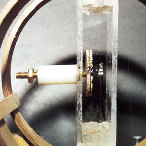
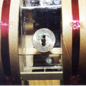
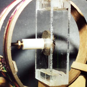 Several Balances were built over a period of time. The original Balance itself was built according to the published directions but suffered from considerable underdamping which resulted in poor transient response of the control loop and a strong tendency for the control loop to oscillate. On the suggestion of another experimentalist, Ed Phillips of San Gabriel, CA, a silver half-dollar is used instead of a high-purity copper penny for magnetic damping. A mounting is included which allows fine tuning of the damping factor. If you have a piece of electronic equipment known as a function generator or something equivalent you can observe some very interesting effects of the Drive Coil set, Balance, and laser. Connect the generator output through a 1.0 kohm resistor to the Drive Coil set.
Adjust the generator for a sine wave output of just below 1 Hz, with the minimum amplitude output. Install and align the Nulling Magnet Assembly, direct the laser spot on a nearby wall and adjust the generator amplitude so the spot moves back and forth by a few inches. Slowly increase the frequency without changing the amplitude and note that the magnitude of the deflection increases substantially, reaching a maximum at some frequency, and then decreases again. If the magnitude exceeds a few feet (for a ten to twenty foot distant wall), decrease the generator amplitude to prevent damage to the nylon thread. The maximum deflection is obtained at the so-called "resonant frequency" of the Balance and is a function of the sensor magnet and mirror masses, their radial location relative twist axis as defined by the nylon thread, and the "springiness" of the nylon thread. The Balance described on these pages resonates at about 4 Hz without the nulling magnets in place; if the nulling magnet is carefully adjusted, the restoring force provided by the component of the earth's magnetic field which is parallel to 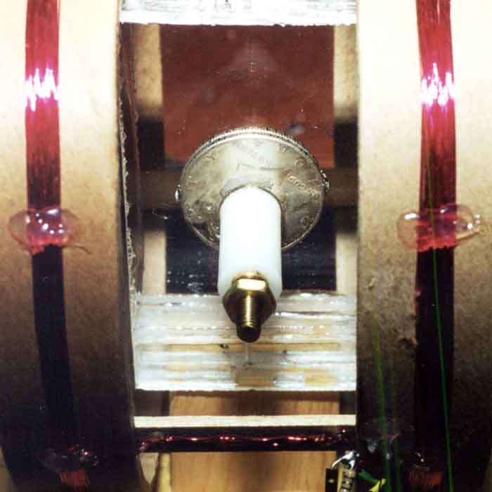 the sensor's magnetic moment is markedly reduced and the sensitivity of the TBM, i.e., the deflection for a given change in field perpendicular to the sensor's moment is greatly increased and the resonant frequency falls to just below 1 Hz.
The deflection magnitude at resonance relative to the magnitude away from resonance is related to the so-called "quality factor" or "Q" of the mechanical system. (This term should bring back memories of freshman physics - both good and bad.) The Q is determined by damping of the system created by friction in the thread, air resistance, and eddy currents induced in the coin. The magnitude of the deflection at resonance compared to that at very low frequency is directly related to the Q and can be modified significantly by advancing or withdrawing the damping coin on its threaded rod. The Q also relates to how quickly oscillations die away when the balance suffers a sharp perturbation. You can see the damped oscillations by changing the generator to give a square wave output of about 0.25-0.5 Hz. The spot will jump from one position to another and will wiggle about those positions for a short period of time (at about the resonant frequency). The higher the 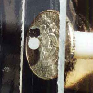 Q, the longer the wiggling will last, and the more "under-damped" the system is called. If the damping could be increased so that fewer wiggles occur then the system would be called either "critically-damped" or "over-damped", depending on just how much damping exists. In the TBM used here, the full range of damping can be obtained quite easily.
