
Here is a description of a simple optical position detector which provides an electrical signal related to the location of the spot of red laser light relatively independent of the absolute intensity of that laser light.
| Home | Graph Data | Text Data | Layout | Detector | Laser | Coil | Electronics | Enclosure | Acquisition | Linearity Analysis | Harmonic Analysis | References | Operator Log |
 |
Here is a description of a simple optical position detector which provides an electrical signal related to the location of the spot of red laser light relatively independent of the absolute intensity of that laser light. |
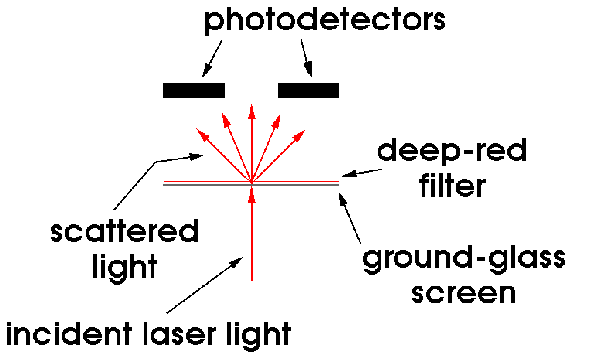 My thinking on an optical position detector began with a linear array of photo detectors tied to some interface circuitry to yield a position-controlled voltage. This was quickly discarded as overly complicated in favor of only two photo detectors located some distance behind a ground glass screen and separated from each other by approximately the same distance. The screen is illuminated by the laser spot and the scattered light reaches the two detectors. The two detectors will receive varying amounts of light depending upon the position of the spot along the line defined by them. The difference in the amount of light received by these two detectors is directly related to the position of the spot of light when it is between them.
a red cellophane filter is placed between the ground glass screen and the CdS photo-conductive detectors to reduce their sensitivity to ambient light. Actually, several layers were used to achieve the necessary depth of color and with this addition the detector is quite immune to room lighting.
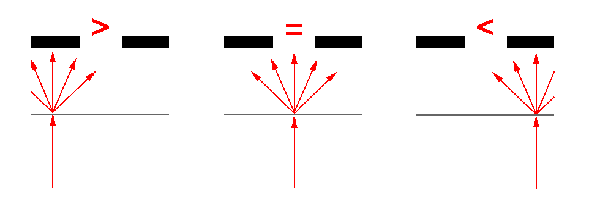 As can be seen in the figure on the right, when the laser spot is located left of center, the left most detector receives a greater share of illumination and vice versa. As will be seen in the description of the electronics package, biasing the photodetectors, taking the difference of the resulting voltages, and performing low-pass filtering to remove the ever present 60 Hz signal results in a strong, robust, and clean position signal.
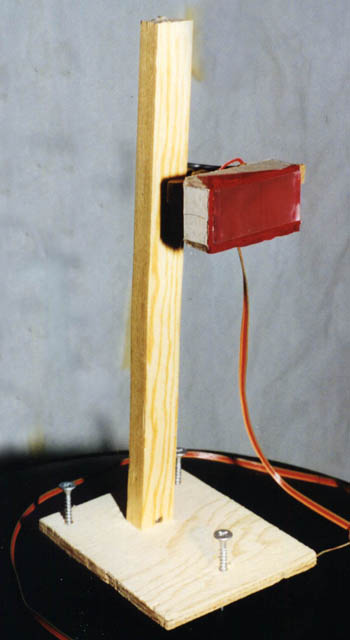
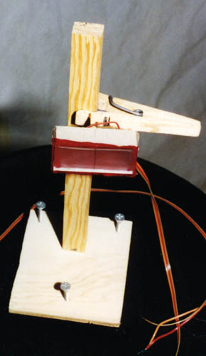 The detector is built of heavy cardboard shaped into a shallow, long box without a face. The two photodetectors are attached to the inside rear wall using hot glue; they are located on the horizontal midline and symmetrically spaced apart by a few centimeters about the vertical midline. Several layers of red cellophane and one piece of ground glass cover the open face and are also attached with hot glue. a fine vertical line is drawn with a pencil on the exposed ground glass surface midway between the two photodetectors for convenience in positioning the laser spot. a wooden clothespin is attached to the outside rear wall using a small spacer block and more hot glue. This humble scheme is remarkably effective at positioning the detector reliably. It shouldn't come as a surprise that the base of the detector enjoys the three-point leveling system and it comes in very handy to true up the vertical mounting stalk.
In Version 2, a new signal has been generated which corresponds to the sum of the photodetector outputs, as contrasted with the difference of them. This sum signal is used to assess the state of the laser or to identify if the laser spot has been deflected off of the detector face, although this simple signal cannot distinguish between the two cases.
Several versions of detector have been developed and tested with an eye toward linearizing the output with regard to the spot position or equivalently deflection angle. I have found that the linearity increases with the depth of the detector box for a given box width. This can easily understood on the basis of geometric arguments. The scattered light forms an approximately spherical source with brightness falling off with an inverse distance squared dependence (between the spot and detector). With depths shallower than two radii, the brightness at one detector falls off faster than it rises at the other detector as the spot sweeps across the detector face. A deeper box results in a smaller signal due to overall greater distance between the face and photocells but there is plenty of signal (to noise) and the loss is more than made up by the gain in linearity.
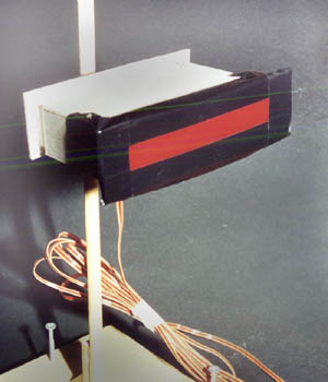
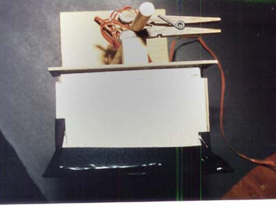 One of these later version detectors with a larger depth to width ratio is shown here in the accompaning two figures.
Home |
Graph Data |
Text Data |
Layout |
Detector |
Laser |
Coil |
Electronics |
Enclosure |
Acquisition
Linearity Analysis |
Harmonic Analysis |
References |
Operator Log
![]()
 Copyright © 2001, 2002, 2003 XTR Systems, LLC
All Rights Reserved
Send comments to: Webmaster