In order to take a high speed photograph one must either have a very fast shutter or light source. We followed the latter course and first examined an commercial flash unit to determine its light profile. This was accomplished by exposing a phototransistor connected in an emitter follower  configuration with a relatively low impedance emitter resistor to the flash and viewing the resistor voltage with an oscilloscope. Since we did not have a fast digitizer or camera available the observed trace was roughly hand sketched. The figure to the left shows the observed data. The phototransistor circuit appears in the right of the figure and the light curve of the commercial flash unit is shown at the lower left. It can be seen that the pulse length is around 175 µs which is far too long. For example, a 130 m s-1 object (295 mph) will travel 22 mm in that time. We set about to build our own light with a significantly shorter pulse length.
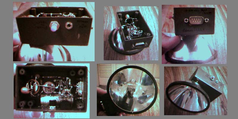
Fortunately, a U-shaped xenon flash lamp and companion pulse transformer were available from a local Radio Shack (and still are although the pulse transformer is now a special order item) and there were a few high voltage capacitors in the junk box. A high voltage (several hundred volt) power supply was also laying about which was built for another project at least twenty years ago. A very nice reflector was obtained from a hand-held lantern, drilled out to pass the flash lamp, and attached to a small plastic box with epoxy.
The electrical components were mounted free-standing inside the box, a male DB-9 connector was used to connect to the high voltage source, a "short-to-fire" connector was implemented with a female 1/8" phone jack, and a momentary contact switch was utilized as a "push-to-test" button. The following figure shows a collection of views of the home-made strobe flash unit.
The resulting light curve for this home-made unit is also shown in the figure at the top of this page. The pulse length is approximately 30 µs, about one-sixth of the commercial unit. The relative areas of the two curves can be compared to determine the change in relative exposure. The home-made unit emits about one-fifth of the total light of the commercial unit.
The electrical schematic of the strobe light is shown in the figure below. The high voltage (400 VDC, maximum) is applied directly to the main capacitor (4 µF, 450 V) which is directly connected to the main terminals of the flash lamp. The connections between the capacitor and lamp are relatively heavy, low inductance straps to minimize their effect on the flash's pulse length. The pulse transformer is set in a step-up configuration and its high voltage secondary is connected to the ionization electrode of the lamp. The low(er) voltage primary is connected to a smaller capacitor (0.02 µF, 300 V) through a very high impedance voltage divider. In operation, this capacitor charges to one-half the main voltage through the divider and is discharged through the transformer's primary by momentarily shorting the divider to ground by a silicon-controlled rectifier (SCR, 400 PIV, 4 A)
The rest of the circuit is a single transistor amplifier and pulse-forming circuit which generates a sharp pulse with sufficient current to trigger the SCR's gate. It will be activated either by depressing the "push-to-test" switch or by shorting out the contacts of the jack.
