With the signals generated by the timing stations and an old surplus multi-function counter was used to measure the time it took for a projectile to traverse the distance between them and calculate the average speed over that distance. Another interest of ours was to actually photograph those projectiles in flight. One of the challenges in performing high speed photography is accurately knowing when the projectile will be in the camera's field of view so that the strobe light can be triggered.
If the camera is located "down range" from the second station at a distance equal to the distance between the stations then the triggering is made relatively simple. The time period it takes the projectile to traverse the inter-station space is used as a delay after the second station's signal occurs and generate the strobe trigger. Any minor timing adjustments that might be necessary can be made by moving the camera along the flight path.
There are several ways to create the required time delay. For example, a capacitor, initially discharged, can be charged at a constant rate while the projectile flies between the stations and then be discharged at the same rate when it passes the second station. The desired time occurs when the capacitor is fully discharged. Alternately, a high frequency oscillator can be used to cause a digital counter to alternately count up and then down during the appropriate periods. Both of these schemes, and many others, can also provide the experimenter with a means of determining the actual projectile speed to accompany the photograph.
The ready availability of a Motorola 68HC11 Microcontroller Evaluation Board (EVB) suggested an opportunity to accomplish the necessary measurement and signal generation while learning a new technology. The 68HC11 has a timer system based on a free-running 16 bit counter with a four-stage programmable prescaler. The clock for this system is derived from the main microcontroller (MCU) clock. Several input-capture functions are available to record or latch the time when a selected transition is detected at a respective timer input pin. Another series of output-compare functions are present for generating output signals with a high degree of control.
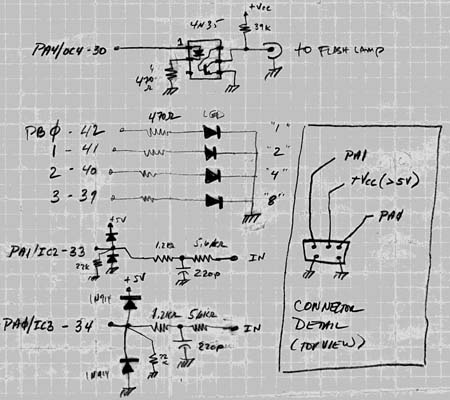
The interface circuitry is shown in the figure to the left. At the top is the optocoupler interface to the strobe light. This interface is capable of driving commercial flash lights which essentially require a short circuit between the two terminals to trigger the flash. The internal LED is driven by one of the MCU's output signals, (Port A #3) through a current limiting resistor. Below this and to the left is the display LED circuit. Each LED is driven from a particular Port B signal through a current limiting resistor. These LEDs have proven very useful in debuging the microprogram and actual operation. Below the LED circuit are the two input conditioning circuits for the trigger station signals. They may seem uneccessarily complicated but they are neither. Bad design of off-board connections is a prime failure mode of digital circuitry and very time-consuming to debug. First encountered by incoming signals is a lowpass T-filter; neither the resistor nor the capacitor values are critical. Next in line is a high value resistor to ground to ensure a guaranteed state when there is no connection and to bleed off static charges. The two diodes are connected directly to the positive supply voltage and ground; their purpose is to shunt discharge and other currents into the large power supply components and away from the MCU in conjunction with the current limiting provided by the T-filter.
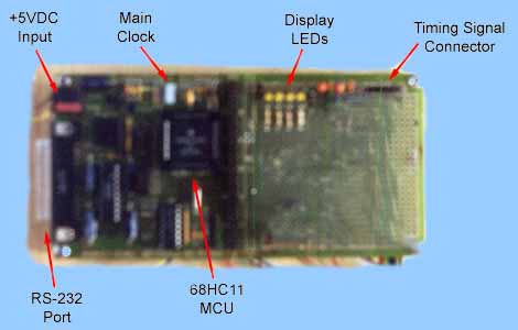
An image of the EVB is shown on the right with the major items relative to this project identified.
The 68HC11 assembly program can be viewed in a separate window. This program accepts the two digital inputs and delivers one digital output, all previously identified. The inputs correspond to projectile crossings across two timing stations. The program measures the time interval between the two crossings and supplies a single pulse which starts at a time after the second event which equals the time interval between the two events. The single output pulse is fixed length of 1 millisecond (msec). The value of the time interval is emitted from the RS-232 serial port as a decimal number of microseconds. Connecting a spare "dumb" terminal or computer with a terminal emulator to the serial port allows easy display of the "time of passage" of the projectile.
